Ethernet Frame Fields (21.2.4)
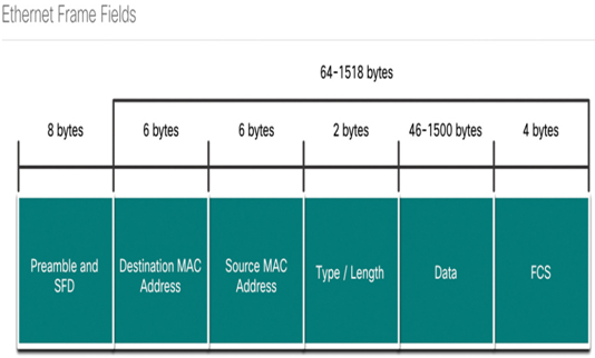
The minimum Ethernet frame size is 64 bytes and the expected maximum is 1518 bytes. This includes all bytes from the destination MAC address field through the frame check sequence (FCS) field. The preamble field is not included when describing the size of the frame.
Note:
The frame size may be larger if additional requirements are included, such as VLAN tagging. VLAN tagging is beyond the scope of this course.
Any frame less than 64 bytes in length is considered a “collision fragment” or “runt frame” and is automatically discarded by receiving stations. Frames with more than 1500 bytes of data are considered “jumbo” or “baby giant frames”.
If the size of a transmitted frame is less than the minimum, or greater than the maximum, the receiving device drops the frame. Dropped frames are likely to be the result of collisions or other unwanted signals. They are considered invalid. Jumbo frames are usually supported by most Fast Ethernet and Gigabit Ethernet switches and NICs.
Figure 21-5 shows each field in the Ethernet frame.

Figure 21-5 Ethernet Frame Structure and Field Size
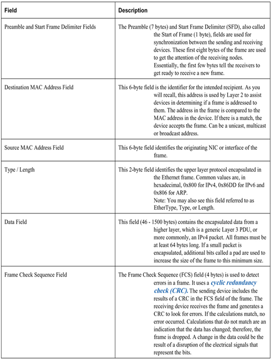
Refer to Table 21-1 for more information about the function of each field.
Table 21-1 Ethernet Frame Fields Detail

Check Your Understanding – Ethernet Frame (21.2.5)
Refer to the online course to complete this activity.
Lab – View Captured Traffic in Wireshark (21.2.6)
In this lab, you will complete the following objectives:
• Download and install Wireshark.
• Capture and analyze ARP data in Wireshark.
• View the ARP cache entries on the PC.
Refer to the online course to complete this lab.
Lab – Use Wireshark to Examine Ethernet Frames (21.2.7)
In this lab, you will complete the following objectives:
Part 1: Examine the Header Fields in an Ethernet II Frame
Part 2: Use Wireshark to Capture and Analyze Ethernet Frames
Refer to the online course to complete this lab.
Ethernet technology relies on MAC addresses to function. MAC addresses are used to identify the frame source and destination.
MAC Address and Hexadecimal (21.3.1)
In networking, IPv4 addresses are represented using the decimal base ten number system and the binary base 2 number system. IPv6 addresses and Ethernet addresses are represented using the hexadecimal base sixteen number system. To understand hexadecimal, you must first be very familiar with binary and decimal.
The hexadecimal numbering system uses the numbers 0 to 9 and the letters A to F.
An Ethernet MAC address consists of a 48-bit binary value. Hexadecimal is used to identify an Ethernet address because a single hexadecimal digit represents four binary bits. Therefore, a 48-bit Ethernet MAC address can be expressed using only 12 hexadecimal values.
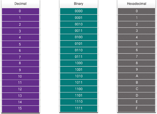
Figure 21-6 compares the equivalent decimal and hexadecimal values for binary 0000 to 1111.

Figure 21-6 Decimal to Binary to Hexadecimal Conversion
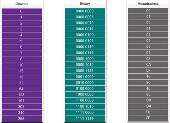
Given that 8 bits (one byte) is a common binary grouping, binary 00000000 to 11111111 can be represented in hexadecimal as the range 00 to FF, as shown in the Figure 21-7.

Figure 21-7 Selected Examples of Decimal to Binary to Hexadecimal Conversions
When using hexadecimal, leading zeroes are always displayed to complete the 8-bit representation. For example, in the table, the binary value 0000 1010 is shown in hexadecimal as 0A.
Hexadecimal numbers are often represented by the value preceded by 0x (e.g., 0x73) to distinguish between decimal and hexadecimal values in documentation.
Hexadecimal may also be represented by a subscript 16, or the hex number followed by an H (e.g., 73H).
You may have to convert between decimal and hexadecimal values. If such conversions are required, convert the decimal or hexadecimal value to binary, and then to convert the binary value to either decimal or hexadecimal as appropriate.
