Upon completion of this chapter, you will be able to answer the following questions:
- What is the purpose and functions of the physical layer in the network?
- What are characteristics of the physical layer?
- What are the basic characteristics of copper cabling?
- How is UTP cable used in Ethernet networks?
- What is fiber-optic cabling and what are its main advantages over other media?
This chapter uses the following key terms. You can find the definitions in the Glossary.
wireless access point (AP)
Network interface cards (NICs)
International Organization for Standardization (ISO)
Telecommunications Industry Association/Electronic Industries Association (TIA/EIA)
International Telecommunication Union (ITU)
American National Standards Institute (ANSI)
Institute of Electrical and Electronics Engineers (IEEE)
Encoding
Manchester encoding
Bandwidth
Throughput
Goodput
Electromagnetic interference (EMI)
Crosstalk
Unshielded twisted-pair (UTP)
Shielded twisted-pair (STP)
Coaxial cable
fiber-optic cable
Introduction (30.0)
I have a friend I’d like you to meet. Her name is Halimah. She just started working as a junior member of the IT department of a large oil and gas firm that specializes in exploration and production. Her company has a multi-building headquarters and several branch offices throughout Nigeria.
In this module, you will learn about the physical layer of networks. Halimah already knows this information and she needs to use it to better understand the way the network at headquarters is constructed.
Are you ready to get started?
Purpose of the Physical Layer (30.1)
All data being transferred over a network must be represented on a medium by the sending node and interpreted on a medium by the receiving node. The physical layer is responsible for these functions. In this topic, the physical layer will be explored.
The Physical Connection (30.1.1)
Whether connecting to a local printer in the home or a website in another country, before any network communications can occur, a physical connection to a local network must be established. A physical connection can be a wired connection using a cable or a wireless connection using radio waves.
The type of physical connection used depends upon the setup of the network. For example, in many corporate offices, employees have desktop or laptop computers that are physically connected, via cable, to a shared switch. This type of setup is a wired network. Data is transmitted through a physical cable.
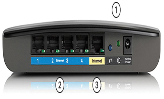
In addition to wired connections, many businesses also offer wireless connections for laptops, tablets, and smartphones. With wireless devices, data is transmitted using radio waves. Wireless connectivity is common as individuals and businesses alike discover its advantages. Devices on a wireless network must be connected to a wireless access point (AP) or wireless router like the one shown in Figure 30-1.

Figure 30-1 Wireless Router
These are the components of an access point:
1. The wireless antennas (These are embedded inside the router version shown in Figure 30-1.)
2. Several Ethernet switchports
3. An internet port
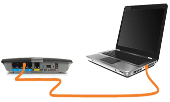
Similar to a corporate office, most homes offer both wired and wireless connectivity to the network. Figure 30-2 shows a home router and a laptop connecting to the local area network (LAN).

Figure 30-2 Wired Connection to a Wireless Router
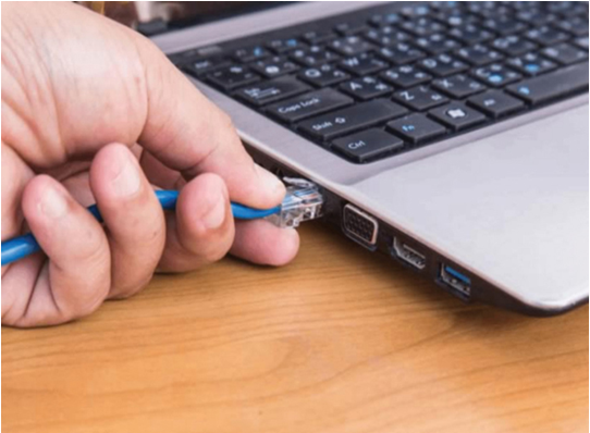
Network interface cards (NICs) connect a device to the network. Ethernet NICs are used for a wired connection, as shown in Figure 30-3, whereas wireless local area network (WLAN) NICs are used for wireless. An end-user device may include one or both types of NICs. A network printer, for example, may only have an Ethernet NIC, and therefore, must connect to the network using an Ethernet cable. Other devices, such as tablets and smartphones, might only contain a WLAN NIC and must use a wireless connection.
Not all physical connections are equal, in terms of the performance level, when connecting to a network.

Figure 30-3 Wired Connection Using an Ethernet NIC
