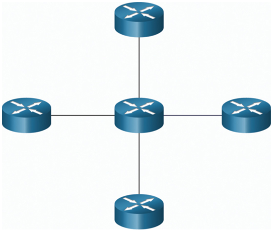
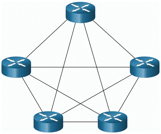
WANs are commonly interconnected using three common physical WAN topologies
A point-to-point link (Figure 31-3), in the simplest and most common WAN topology. It consists of a permanent link between two endpoints.

Figure 31-3 Point-to-Point Topology
Figure 31-4 shows a WAN version of the star topology in which a central site interconnects branch sites through the use of point-to-point links. Branch sites cannot exchange data with other branch sites without going through the central site.

Figure 31-4 Hub and Spoke Topology
A mesh topology (Figure 31-5) provides high availability but requires that every end system is interconnected to every other system. Therefore, the administrative and physical costs can be significant. Each link is essentially a point-to-point link to the other node.

Figure 31-5 Mesh Topology
A hybrid is a variation or combination of any topologies. For example, a partial mesh is a hybrid topology in which some, but not all, end devices are interconnected.
Point-to-Point WAN Topology (31.1.4)
Physical point-to-point topologies directly connect two nodes, as shown in Figure 31-6. In this arrangement, two nodes do not have to share the media with other hosts. Additionally, when using a serial communications protocol such as Point-to-Point Protocol (PPP), a node does not have to make any determination about whether an incoming frame is destined for it or another node. Therefore, the logical data link protocols can be very simple, as all frames on the media can only travel to or from the two nodes. The node places the frames on the media at one end and those frames are taken from the media by the node at the other end of the point-to-point circuit.

Figure 31-6 Point-to-Point WAN Topology
Note:
A point-to-point connection over Ethernet requires the device to determine if the incoming frame is destined for this node.
A source and destination node may be indirectly connected to each other over some geographical distance using multiple intermediary devices. However, the use of physical devices in the network does not affect the logical topology, as illustrated in the figure. In Figure 31-7, adding intermediary physical connections may not change the logical topology. The logical point-to-point connection is the same.

Figure 31-7 Logical and Physical WAN Topology
In multiaccess LANs, end devices (i.e., nodes) are interconnected using star or extended star topologies, as shown in the figure. In this type of topology, end devices are connected to a central intermediary device, in this case, an Ethernet switch. An extended star extends this topology by interconnecting multiple Ethernet switches. The star and extended topologies are easy to install, very scalable (easy to add and remove end devices), and easy to troubleshoot. Early star topologies interconnected end devices using Ethernet hubs.
At times there may be only two devices connected on the Ethernet LAN. An example is two interconnected routers. This would be an example of Ethernet used on a point-to-point topology.
