This topic will introduce the role of the router in the routing process and an introduction their use of routing tables for forward packets.
Router Packet Forwarding Decision (32.2.1)
The previous topic discussed host routing tables. Most networks also contain routers, which are intermediary devices. Routers also contain routing tables. This topic covers router operations at the network layer. When a host sends a packet to another host, it consults its routing table to determine where to send the packet. If the destination host is on a remote network, the packet is forwarded to the default gateway, which is usually the local router.
What happens when a packet arrives on a router interface?
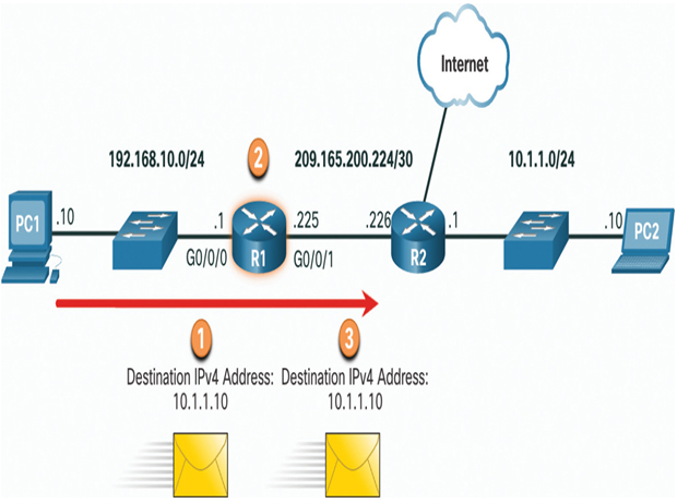
The router examines the destination IP address of the packet and searches its routing table to determine where to forward the packet. The routing table contains a list of all known network addresses (prefixes) and where to forward the packet. These entries are known as route entries or routes. The router will forward the packet using the best (longest) matching route entry. Refer to Figure 32-4 for an example of this forwarding process.

Figure 32-4 Packet Forwarding Process
1. Packet arrives on the Gigabit Ethernet 0/0/0 interface of router R1. R1 de-encapsulates the Layer 2 Ethernet header and trailer.
2. Router R1 examines the destination IPv4 address of the packet and searches for the best match in its IPv4 routing table. The route entry indicates that this packet is to be forwarded to router R2.
3. Router R1 encapsulates the packet into a new Ethernet header and trailer, and forwards the packet to the next hop router R2.
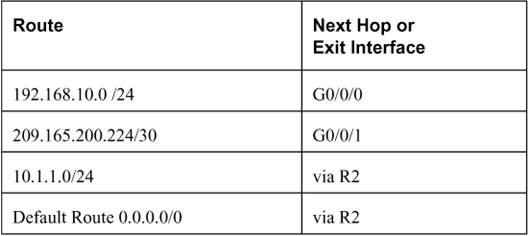
Table 32-1 shows the pertinent information from the R1 routing table.

IP Router Routing Table (32.2.2)
The routing table of the router contains network route entries listing all the possible known network destinations.
The routing table stores three types of route entries:
• Directly-connected networks — These network route entries are active router interfaces. Routers add a directly connected route when an interface is configured with an IP address and is activated. Each router interface is connected to a different network segment. In the figure, the directly-connected networks in the R1 IPv4 routing table would be 192.168.10.0/24 and 209.165.200.224/30.
• Remote networks — These network route entries are connected to other routers. Routers learn about remote networks either by being explicitly configured by an administrator or by exchanging route information using a dynamic routing protocol. In the figure, the remote network in the R1 IPv4 routing table would be 10.1.1.0/24.
• Default route — Like a host, most routers also include a default route entry, a gateway of last resort. The default route is used when there is no better (longer) match in the IP routing table. In the figure, the R1 IPv4 routing table would most likely include a default route to forward all packets to router R2.
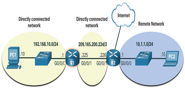
Figure 32-5 identifies the directly connected and remote networks of router R1.

Figure 32-5 Example Topology of Directly Connected and Remote Networks
In Figure 32-5, R1 has two directly connect networks:
- 192.168.10.0/24
- 209.165.200.224/30
R1 also has remote networks (i.e. 10.1.1.0/24 and the internet) that it can learn about.
A router can learn about remote networks in one of two ways:
- Manually — Remote networks are manually entered into the route table using static routes.
- Dynamically — Remote routes are automatically learned using a dynamic routing protocol.
