Static GUA Configuration on a Windows Host (33.2.2)
Manually configuring the IPv6 address on a host is similar to configuring an IPv4 address.
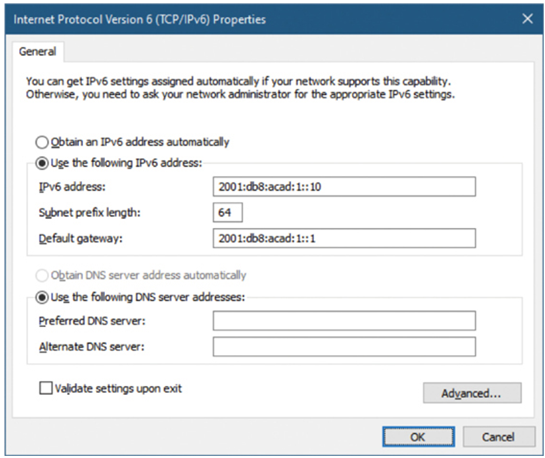
As shown in Figure 33-8, the default gateway address configured for PC1 is 2001:db8:acad:1::1. This is the GUA of the R1 GigabitEthernet interface on the same network. Alternatively, the default gateway address can be configured to match the LLA of the GigabitEthernet interface. Using the LLA of the router as the default gateway address is considered best practice. Either configuration will work.

Figure 33-8 Manually Configuring IPv6 Addressing on a Windows Host
Just as with IPv4, configuring static IPv6 addresses on clients does not scale to larger environments. For this reason, most network administrators in an IPv6 network will enable dynamic assignment of IPv6 addresses.
There are two ways in which a device can obtain an IPv6 GUA automatically:
• Stateless Address Autoconfiguration (SLAAC)
• Stateful DHCPv6
SLAAC and DHCPv6 are covered in the next section.
Note
When DHCPv6 or SLAAC is used, the LLA of the router will automatically be specified as the default gateway address.
Static Configuration of a Link-Local Unicast Address (33.2.3)
Configuring the LLA manually lets you create an address that is recognizable and easier to remember. Typically, it is only necessary to create recognizable LLAs on routers. This is beneficial because router LLAs are used as default gateway addresses and in routing advertisement messages, the messages sent by dynamic routing protocols.
LLAs can be configured manually using the ipv6 address ipv6-link-local-address link-local command. When an address begins with this hextet within the range of fe80 to febf, the link-local parameter must follow the address.
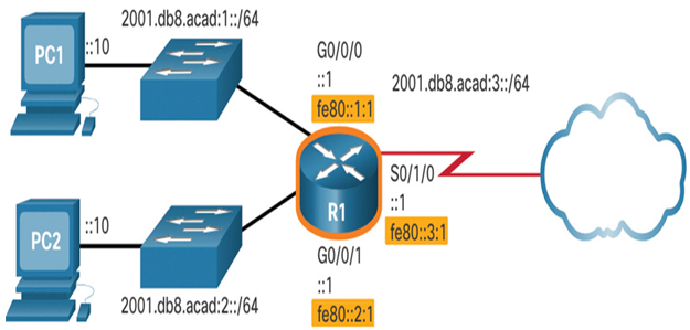
Figure 33-9 shows an example topology with LLAs on each interface.

Figure 33-9 IPv6 Addressing Topology with LLAs
Statically configured LLAs are used to make them more easily recognizable as belonging to router R1. In this example, all the interfaces of router R1 have been configured with an LLA that begins with fe80::1:n and a unique right-most digit n. The 1 represents router R1.
Following the same syntax as router R1, if the topology included router R2, it would have its three interfaces configured with the LLAs fe80::2:1, fe80::2:2, and fe80::2:3.
Note
The exact same LLA could be configured on each link as long as it is unique on that link. This is because LLAs only have to be unique on that link. However, common practice is to create a different LLA on each interface of the router to make it easy to identify the router and the specific interface.
Syntax Checker—GUA and LLA Static Configuration (33.2.4)
Refer to the online course to complete this activity.
