Depending upon the operating system, a device may use a randomly generated interface ID instead of using the MAC address and the EUI-64 process. Beginning with Windows Vista, Windows uses a randomly generated interface ID instead of one created with EUI-64. Windows XP and previous Windows operating systems used EUI-64.
After the interface ID is established, either through the EUI-64 process or through random generation, it can be combined with an IPv6 prefix in the RA message to create a GUA, as shown in Example 33-4.
Example 33-4 Random 64-bit Generated Interface ID
C:>
ipconfig
Windows IP Configuration
Ethernet adapter Local Area Connection:
Connection-specific DNS Suffix . :
IPv6 Address. . . . . . . . . . . :
2001:db8:acad:1:
50a5:8a35:a5bb:66e1
Link-local IPv6 Address . . . . . : fe80::50a5:8a35:a5bb:66e1
Default Gateway . . . . . . . . . : fe80::1
C:>
Note
To ensure the uniqueness of any IPv6 unicast address, the client may use a process known as duplicate address detection (DAD). This is similar to an ARP request for its own address. If there is no reply, then the address is unique.
Check Your Understanding—Dynamic Addressing for IPv6 GUAs (33.3.8)
Refer to the online course to complete this activity.
Dynamic Addressing for IPv6 LLAs (33.4)
This section discusses how a device automatically creates an IPv6 link-local address.
All IPv6 devices must have an IPv6 LLA. Like IPv6 GUAs, you can also create LLAs dynamically. Regardless of how you create your LLAs (and your GUAs), it is important that you verify all IPv6 address configuration. This topic explains dynamically generated LLAs and IPv6 configuration verification.
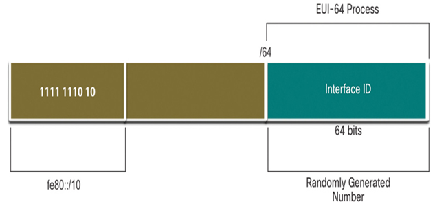
Figure 33-16 shows the LLA is dynamically created using the fe80::/10 prefix and the interface ID using the EUI-64 process, or a randomly generated 64-bit number.

Figure 33-16 Dynamic Creation of an LLA
Dynamic LLAs on Windows (33.4.2)
Operating systems, such as Windows, will typically use the same method for both a SLAAC-created GUA and a dynamically assigned LLA. See the highlighted areas in Examples 33-5 and 33-6 that were shown previously.
Dynamic LLAs on Cisco Routers (33.4.3)
Cisco routers automatically create an IPv6 LLA whenever a GUA is assigned to the interface. By default, Cisco IOS routers use EUI-64 to generate the interface ID for all LLAs on IPv6 interfaces. For serial interfaces, the router will use the MAC address of an Ethernet interface. Recall that an LLA must be unique only on that link or network. However, a drawback to using the dynamically assigned LLA is its long interface ID, which makes it challenging to identify and remember assigned addresses. Example 33-7 displays the MAC address on the GigabitEthernet 0/0/0 interface of router R1. This address is used to dynamically create the LLA on the same interface, and also for the Serial 0/1/0 interface.
To make it easier to recognize and remember these addresses on routers, it is common to statically configure IPv6 LLAs on routers.
Verify IPv6 Address Configuration (33.4.4)
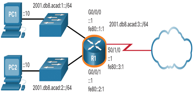
Figure 33-17 shows the example topology.

Figure 33-17 IPv6 Addressing Topology
The show ipv6 interface brief command in Example 33-8 displays the MAC address of the Ethernet interfaces. EUI-64 uses this MAC address to generate the interface ID for the LLA. Additionally, the show ipv6 interface brief command displays abbreviated output for each of the interfaces. The [up/up] output on the same line as the interface indicates the Layer 1/Layer 2 interface state. This is the same as the Status and Protocol columns in the equivalent IPv4 command.
Notice that each interface has two IPv6 addresses. The second address for each interface is the GUA that was configured. The first address, the one that begins with fe80, is the link-local unicast address for the interface. Recall that the LLA is automatically added to the interface when a GUA is assigned.
Also, notice that the R1 Serial 0/1/0 LLA is the same as its GigabitEthernet 0/0/0 interface. Serial interfaces do not have Ethernet MAC addresses, so Cisco IOS uses the MAC address of the first available Ethernet interface. This is possible because link-local interfaces only have to be unique on that link.
As shown in Example 33-9, the show ipv6 route command can be used to verify that IPv6 networks and specific IPv6 interface addresses have been installed in the IPv6 routing table. The show ipv6 route command will only display IPv6 networks, not IPv4 networks.
Within the route table, a C next to a route indicates that this is a directly connected network. When the router interface is configured with a GUA and is in the “up/up” state, the IPv6 prefix and prefix length are added to the IPv6 routing table as a connected route.
Note
The L indicates a Local route, the specific IPv6 address assigned to the interface. This is not an LLA. LLAs are not included in the routing table of the router because they are not routable addresses.
The IPv6 GUA configured on the interface is also installed in the routing table as a local route. The local route has a /128 prefix. Local routes are used by the routing table to efficiently process packets with a destination address of the router interface address.
The ping command for IPv6 is identical to the command used with IPv4, except that an IPv6 address is used. As shown in Example 33-10, the command is used to verify Layer 3 connectivity between R1 and PC1. When pinging an LLA from a router, Cisco IOS will prompt the user for the exit interface. Because the destination LLA can be on one or more of its links or networks, the router needs to know which interface to send the ping to.
Syntax Checker—Verify IPv6 Address Configuration (33.4.5)
Refer to the online course to complete this activity.
Packet Tracer—Configure IPv6 Addressing (33.4.6)
In this activity, you will practice configuring IPv6 addresses on a router, servers, and clients. You will also practice verifying your IPv6 addressing implementation.
Refer to the online course to complete this activity.
