Since the router is just a specialized computer, the boot process is the same as most computers.
Before beginning any equipment installation, it is important to be sure to read the Quick Start guide and other documentation that is included with the device. The documentation contains important safety and procedural information.
Step 1. Securely mount the device to the rack (Figure 35-18).
Note
The Figure 35-18 shows a typical scenario of mounting the chassis in a rack.
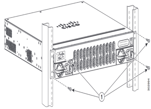
Figure 35-18 Mounting the Chassis in a Rack
Step 2. Ground the device (Figure 35-19).
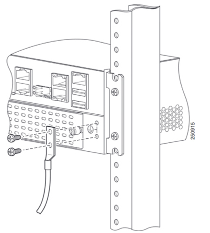
Figure 35-19 Attaching the Ground Wire to the Chassis
Step 3. Connect the power cable (Figure 35-20).
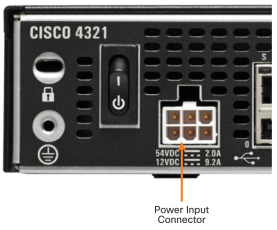
Figure 35-20 Power Input Connector
Step 4. Connect a console cable.
Configure the terminal emulation software on the laptop and connect the laptop to the console port, as shown in Figure 35-21.
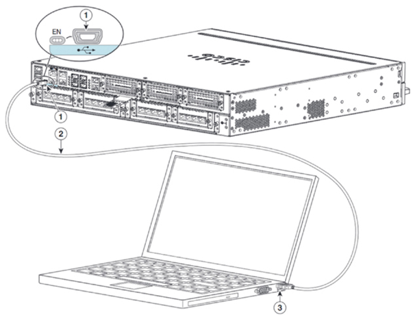
Figure 35-21 Attaching a Console Cable to the Device
Step 5. Turn on the router (Figure 35-22).
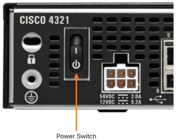
Figure 35-22 The Power Switch
Similar to a Cisco switch, there are several ways to access the command-line interface on a Cisco router. The most common methods are as follows:
• Console—Uses a low-speed serial or USB connection to provide direct connect, out-of-band management access to a Cisco device.
• SSH—Method for remotely accessing a CLI session across an active network interface, including the management interface.
• AUX port—Used for remote management of the router using a dial-up telephone line and modem.
The console port is a physical port located on the router. When using SSH, there must be an active network interface that is configured with a valid IP address for the network. This can be one of the active network interfaces used for network traffic or it can be the management interface. Figure 35-23 shows ports available for management access.
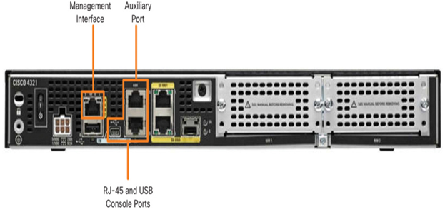
Figure 35-23 Management Configuration Access
In addition to these management ports, routers also have network interfaces to receive and forward IP packets. Most routers have multiple interfaces that are used to connect to multiple networks. Typically, the interfaces connect to various types of networks, as shown in Figure 35-24, which means that different types of media and connectors are required.
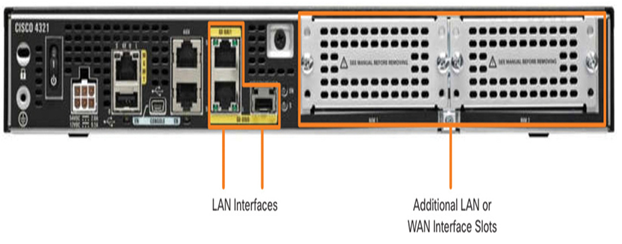
Figure 35-24 LAN and WAN Interfaces
Video—The Cisco Router Boot Process (35.5.3)
Refer to the online course to view this video.
