Have you ever received an email that was addressed to every person at your work or school? This was a broadcast email. Hopefully, it contained information that each of you needed to know. But often a broadcast is not really pertinent to everyone in the mailing list. Sometimes, only a segment of the population needs to read that information.
In an Ethernet LAN, devices use broadcasts and the Address Resolution Protocol (ARP) to locate other devices. ARP sends Layer 2 broadcasts to a known IPv4 address on the local network to discover the associated MAC address. Devices on Ethernet LANs also locate other devices using services. A host typically acquires its IPv4 address configuration using the Dynamic Host Configuration Protocol (DHCP) which sends broadcasts on the local network to locate a DHCP server.
Switches propagate broadcasts out all interfaces except the interface on which it was received. For example, if a switch in Figure 9-7 were to receive a broadcast, it would forward it to the other switches and other users connected in the network.
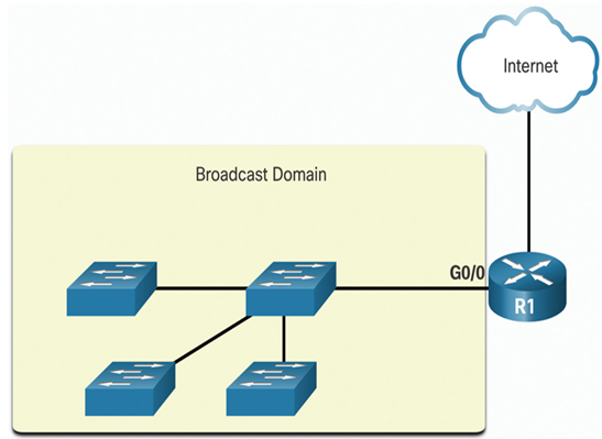
Figure 9-7 Broadcast Domain with Four Switches
Routers do not propagate broadcasts. When a router receives a broadcast, it does not forward it out other interfaces. For instance, when R1 receives a broadcast on its Gigabit Ethernet 0/0 interface, it does not forward out another interface.
Therefore, each router interface connects to a broadcast domain and broadcasts are only propagated within that specific broadcast domain.
Problems with Large Broadcast Domains (9.3.3)
A large broadcast domain is a network that connects many hosts. A problem with a large broadcast domain is that these hosts can generate excessive broadcasts and negatively affect the network. In Figure 9-8, LAN 1 connects 400 users that could generate an excess amount of broadcast traffic. This results in slow network operations due to the significant amount of traffic it can cause, and slow device operations because a device must accept and process each broadcast packet.
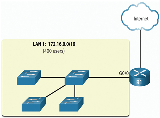
Figure 9-8 Large Broadcast Domain
The solution is to reduce the size of the network to create smaller broadcast domains in a process called subnetting. These smaller network spaces are called subnets.
In Figure 9-9, the 400 users in LAN 1 with network address 172.16.0.0 /16 have been divided into two subnets of 200 users each: 172.16.0.0 /24 and 172.16.1.0 /24. Broadcasts are only propagated within the smaller broadcast domains. Therefore, a broadcast in LAN 1 would not propagate to LAN 2.
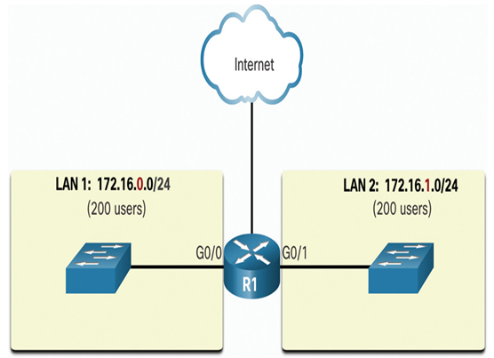
Figure 9-9 Segmenting a Large Broadcast Domain
Notice how the prefix length has changed from a single /16 network to two /24 networks. This is the basis of subnetting: using host bits to create additional subnets.
Note
The terms subnet and network are often used interchangeably. Most networks are a subnet of some larger address block.
Reasons for Segmenting Networks (9.3.4)
Subnetting reduces overall network traffic and improves network performance. It also enables an administrator to implement security policies such as which subnets are allowed or not allowed to communicate together. Another reason is that it reduces the number of devices affected by abnormal broadcast traffic due to misconfigurations, hardware/software problems, or malicious intent.
There are various ways of using subnets to help manage network devices, as shown in Figure 9-10 through 9-12.
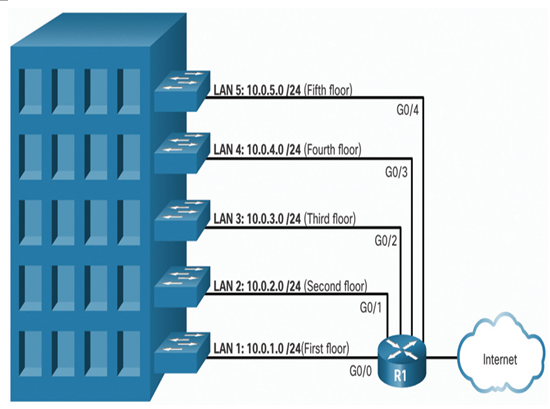
Figure 9-10 Subnetting by Location
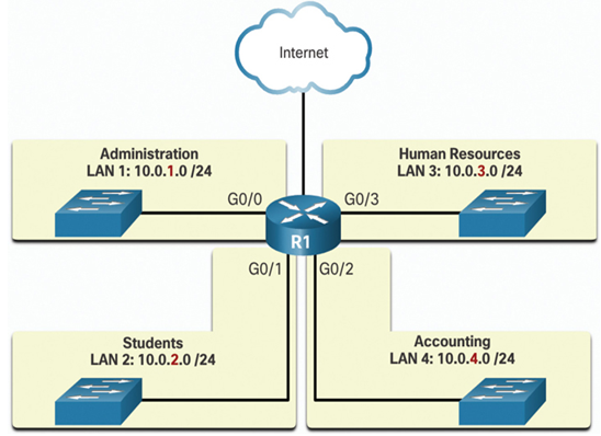
Figure 9-11 Subnetting by Group or Function
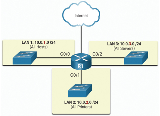
Figure 9-12 Subnetting by Device Type
Network administrators can create subnets using any other division that makes sense for the network. Notice in each figure, the subnets use longer prefix lengths to identify networks.
Understanding how to subnet networks is a fundamental skill that all network administrators must develop. Various methods have been created to help understand this process. Although a little overwhelming at first, pay close attention to the detail and, with practice, subnetting will become easier.
