In contention-based multiaccess networks, all nodes are operating in half-duplex, competing for the use of the medium. However, only one device can send at a time. Therefore, there is a process if more than one device transmits at the same time. Examples of contention-based access methods include the following:
• Carrier sense multiple access with collision detection (CSMA/CD) used on legacy bus-topology Ethernet LANs, shown in Figure 31-11.
• Carrier sense multiple access with collision avoidance (CSMA/CA) used on Wireless LANs.
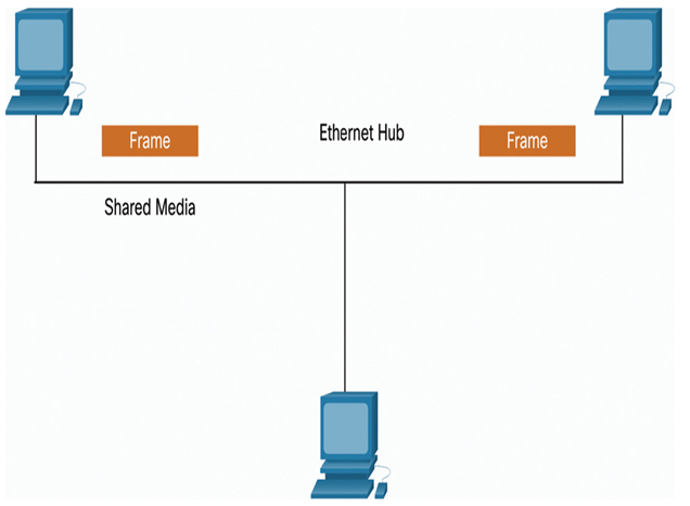
Figure 31-11 Contention-Based Access on Shared Media
In a controlled-based multiaccess network, each node has its own time to use the medium. These deterministic types of legacy networks are inefficient because a device must wait its turn to access the medium. Examples of multiaccess networks that use controlled access include the following:
• Legacy Token Ring (Figure 31-12)
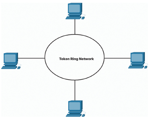
Figure 31-12 Controlled Access on Token Ring
Note:
Today, Ethernet networks operate in full-duplex and do not require an access method.
Contention-Based Access — CSMA/CD (31.2.3)
Examples of contention-based access networks include the following:
• Wireless LAN (uses CSMA/CA)
• Legacy bus-topology Ethernet LAN (uses CSMA/CD)
• Legacy Ethernet LAN using a hub (uses CSMA/CD)
These networks operate in half-duplex mode, meaning only one device can send or receive at a time. This requires a process to govern when a device can send and what happens when multiple devices send at the same time.
If two devices transmit at the same time, a collision will occur. For legacy Ethernet LANs, both devices will detect the collision on the network. This is the collision detection (CD) portion of CSMA/CD. The NIC compares data transmitted with data received, or by recognizing that the signal amplitude is higher than normal on the media. The data sent by both devices will be corrupted and will need to be resent.
Figures 31-13 through Figure 31-15 demonstrate the CSMA/CD process in legacy Ethernet LANs that use a hub.
In Figure 31-13, PC1 has an Ethernet frame to send to PC3. The PC1 NIC needs to determine if any device is transmitting on the medium. If it does not detect a carrier signal (in other words, it is not receiving transmissions from another device), it will assume the network is available to send.
The PC1 NIC sends the Ethernet Frame when the medium is available.
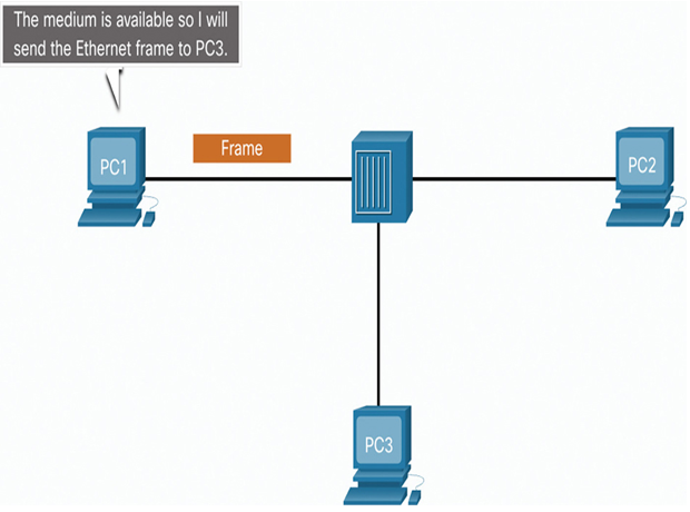
Figure 31-13 PC1 Sends a Frame
In Figure 31-14, the Ethernet hub receives and sends the frame. An Ethernet hub is also known as a multiport repeater. Any bits received on an incoming port are regenerated and sent out all other ports, as shown in the figure.
If another device, such as PC2, wants to transmit, but is currently receiving a frame, it must wait until the channel is clear.
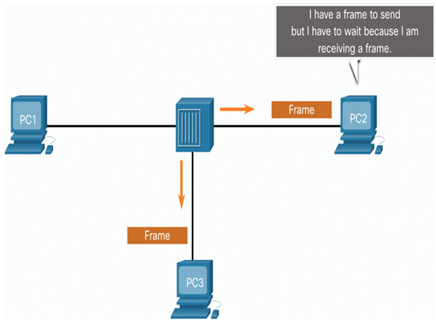
Figure 31-14 The Hub Receives the Frame
In Figure 31-15, all devices attached to the hub will receive the frame. However, because the frame has a destination data link address for PC3, only that device will accept and copy in the entire frame. All other device NICs will ignore the frame.
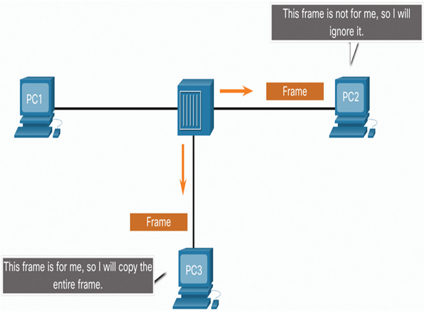
Figure 31-15 The Hub Sends the Frame
