Fiber patch cords are required for interconnecting infrastructure devices. The use of color distinguishes between single-mode and multimode patch cords. A yellow jacket is for single-mode fiber cables and orange (or aqua) for multimode fiber cables.
Figures 30-28 through 30-31 show four types of fiber patch cords.
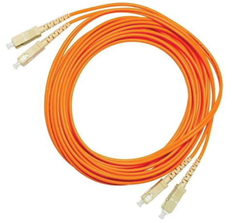
Figure 30-28 SC-SC Multimode Patch Cord
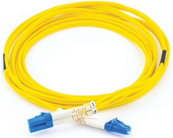
Figure 30-29 LC-LC Single-mode Patch Cord
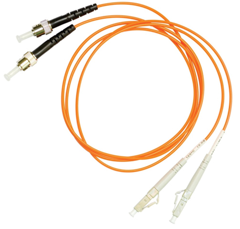
Figure 30-30 ST-LC Multimode Patch Cord
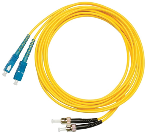
Figure 30-31 SC-ST Single-mode Patch Cord
Note:
Fiber cables should be protected with a small plastic cap when not in use.
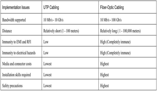
There are many advantages to using fiber-optic cable compared to copper cables. Table 30-3 highlights some of these differences.
At present, in most enterprise environments, optical fiber is primarily used as backbone cabling for high-traffic, point-to-point connections between data distribution facilities. It is also used for the interconnection of buildings in multi-building campuses. Because fiber-optic cables do not conduct electricity and have a low signal loss, they are well suited for these uses.
Table 30-3 UTP and Fiber-Optic Cabling Comparison
Check Your Understanding – Fiber-Optic Cabling (30.5.7)
Refer to the online course to complete this Activity.
The following is a summary of each topic in the chapter and some questions for your reflection.
What Did I Learn in this Module? (30.6.1)
• Purpose of the Physical Layer—Before any network communications can occur, a physical connection to a local network must be established. A physical connection can be a wired connection using a cable or a wireless connection using radio waves. Network Interface Cards (NICs) connect a device to the network. Ethernet NICs are used for a wired connection, whereas WLAN (Wireless Local Area Network) NICs are used for wireless connections. The OSI physical layer provides the means to transport the bits that make up a data link layer frame across the network media. This layer accepts a complete frame from the data link layer and encodes it as a series of signals that are transmitted onto the local media. The encoded bits that comprise a frame are received by either an end device or an intermediary device.
• Physical Layer Characteristics—The physical layer consists of electronic circuitry, media, and connectors developed by engineers. The physical layer standards address three functional areas: physical components, encoding, and signaling. Bandwidth is the capacity at which a medium can carry data. Digital bandwidth measures the amount of data that can flow from one place to another in a given amount of time. Throughput is the measure of the transfer of bits across the media over a given period of time and is usually lower than bandwidth. Latency refers to the amount of time, including delays, for data to travel from one given point to another. Goodput is the measure of usable data transferred over a given period of time. The physical layer produces the representation and groupings of bits for each type of media as follows:
• Copper cable — The signals are patterns of electrical pulses.
• Fiber-optic cable — The signals are patterns of light.
• Wireless — The signals are patterns of microwave transmissions.
