Cisco switches go through a boot process similar to that of your computer or smartphone. Ethernet switches in small networks usually do not require any configuration. They are designed to work “right out of the box.”
Cisco switches, like most switches, are preconfigured to operate in a LAN as soon as they are powered on. All of the interface ports on the switch are active and will begin forwarding traffic immediately when devices are plugged into them. It is important to remember that no security settings are enabled by default. You will need to configure the basic security settings before placing the switch into the network.
The three basic steps for powering up a switch are as follows:
Step 1. Check the components.
Step 2. Connect the cables to the switch.
Step 3. Power up the switch.
Note
You can also attach cables after power is applied.
When the switch is on, the power-on self-test (POST) begins. During POST, the LEDs blink while a series of tests determine that the switch is functioning properly.
POST is completed when the SYST LED rapidly blinks green. If the switch fails POST, the SYST LED turns amber. When a switch fails POST, it is necessary to return the switch for repairs.
When all startup procedures are finished, the Cisco switch is ready to configure.
Step 1. Check the components.
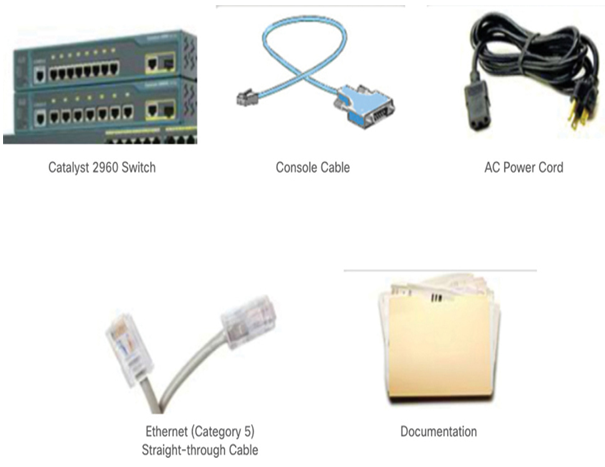
Ensure all the components that came with the switch are available (Figure 35-13). These could include a console cable, power cord, Ethernet cable, and switch documentation.

Figure 35-13 Components for Connecting to a Switch
Step 2. Connect the cables to the switch.
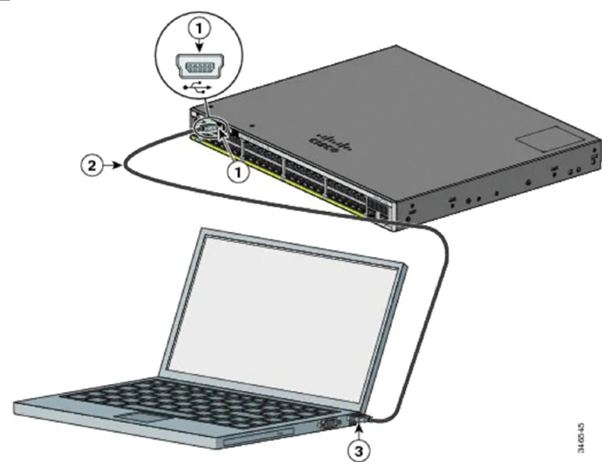
As shown in Figure 35-14, connect the PC to the switch with a console cable and start a terminal emulation session. Connect the AC power cord to the switch and to a grounded AC outlet.

Figure 35-14 Switch to Laptop Console Connection
Step 3. Power up the switch.
Some Cisco switch models do not have an on/off switch, like the Cisco Catalyst 9300 48S switch shown in Figure 35-15. To power on the switch, plug one end of the AC power cord into the switch AC power connector, and plug the other end into an AC power outlet.
Note
The Cisco Catalyst 9300 switch in Figure 35-15 has redundant power supplies in case one fails.

Figure 35-15 Back Panel of the Cisco Catalyst 9300 48S
Video—In-Band and Out-of-Band Device Management (35.3.2)
Refer to the online course to view this video.
In-Band and Out-of-Band Management (35.3.3)
There are two methods to connect a PC to a network device to perform configuration and monitoring tasks: out-of-band management and in-band management.
Out-of-band management requires a computer to be directly connected to the console port of the network device that is being configured. This type of connection does not require the local network connections on the device to be active. Technicians use out-of-band management to initially configure a network device, because until properly configured, the device cannot participate in the network. Out-of-band management is also useful when the network connectivity is not functioning correctly, and the device cannot be reached over the network. Performing out-of-band management tasks requires a terminal emulation client installed on the PC.
Use in-band management to monitor and make configuration changes to a network device over a network connection. For a computer to connect to the device and perform in-band management tasks, at least one network interface on the device must be connected to the network and have an IP address configured on it. Either Telnet, SSH, HTTP, or HTTPS can be used to access a Cisco device for in-band management, monitor the network device, or make configuration changes. Telnet and HTTP send all data, including passwords, in clear text and therefore should only be used in a lab environment.
